3.1 Strain Gage and Aerodynamic Drag Data
3.1 Strain Gage and Aerodynamic Drag Data Further Validate Our Aeroelastic Computer Models

Meteorological (“Met”) mast with anemometers and transmitter.
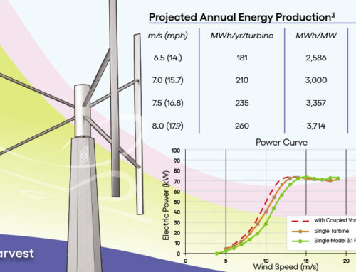
The Pilot Project step in the Technology Readiness Level process (TRL 7) is an enormously important but rarely reached milestone in the commercialization of utility-scale, renewable energy technology. The full-scale prototype going through this step provides real-world data that refines and validates the engineers’ computer models for its design. The strain gauge and other data collected from our Wind Harvester Model 3.1 have delighted our engineering team in how accurately it correlates to their predictions on load, aerodynamic drag, and harmonic resonance.
Testing our Wind Harvester 3.1 requires a relatively windless day with wind speeds averaging only one mph, which we finally met on Monday. Mark Chang and Dr. David Malcolm recently conducted an aerodynamic drag test remotely. The drag test involves measuring the energy needed to motor the turbine at 5, 10, 15, 20, and 30 revolutions per minute (RPM) (skipping 25 RPM). This test gives us information on the inherent drag in the rotor. The resulting energy calculation almost precisely matched our aerodynamic model’s prediction.
We skipped motoring at 25 RPM since our models and collected data showed that is where a harmonic resonance ‘crossing” occurs. We avoid operating in “resonant” zones due to the impact on the wind turbine systems, particularly the rotor. Our designs and data show that the turbine will produce electricity in the operational RPM zone (30-55 RPM) without any resonance issues.
A substantial part of the effort spent on our Model 3.1 went into designing and preparing this data-gathering process. A challenge in collecting data from our Model 3.1 turbine is that most of the data doesn’t necessarily comes from a spinning rotor. We solved this by reusing the Microstrain transmitters on Models 2.0 and 3.0. There are eight of them attached to the rotor components, mostly with powerful magnets or the met mast and tower.
These high-tech, battery-driven tools transmit 36 signals per second to a receiver and antenna located 100 yards away in the turbine’s control cabinet. That data is sent via a fiberoptic cable to the designated computer in the UL building. It is then backed up to Cloud storage.
The primary load and frequency response (harmonic resonance) sensors are tiny “strain gauges” (the size of a fingernail) that are wired to the transmitters. The gauges measure minuscule changes in the movement of the steel and aluminum they are attached to, which provides the wind-created lift and loads on the turbine as well as changes in the “frequency” of the rotating turbine.

Transmitter-RPM-Dat
Transmitter sending RPM data.

Transmitter-wind-speed
Transmitter sending wind speed data.

Transmitter-Strapped-to-Mast
Transmitter strapped to mast and wired to strain gauges covered with tape.

Transmitter-below-support-arm
Transmitter attached with magnets below lower support arm.

Strain-Guages-Lower-Mast
Strain gauges were installed on the lower mast in the shop.

Stain-guage-glued-blade
Small strain gauge glued to blade.
Meteorological-mast-with-anemometers-and-transmitter
Meteorological (“Met”) mast with anemometers and transmitter.

Hall-Effect-RPM-Sensor
Hall Effect RPM Sensors on the driveshaft.
Test the waters disclaimer page here
Contact: Jen Hoover, jhoover@windharvest.com
Wind Harvest International, Inc. is a California-based renewable energy technology company, founded in 2006. The company makes, sells, and develops projects for its Wind Harvester brand of H-type turbines, the only known product designed to harvest the highly energetic, turbulent wind that blows 15-80 feet above the ground. Wind Harvest’s wholly-owned financial subsidiary Wind Harvest Pilot Project Inc. raises funds and loans it to the parent company.